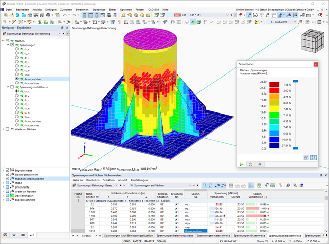
Did you know? When unloading the structural component with a plastic material model, in contrast to the Isotropic | Nonlinear Elastic material model, the strain remains after it has been completely unloaded.
You can select three different definition types:
- Standard (definition of the equivalent stress under which the material plastifies)
- Bilinear (definition of the equivalent stress and strain hardening modulus)
- Stress-strain diagram: definition of polygonal stress-strain diagram
- Option to save / import the diagram
- Interface with MS Excel
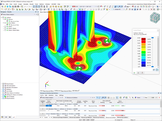
If you release a structural component with a nonlinear elastic material again, the strain goes back on the same path. In contrast to the Isotropic|Plastic material model, there is no strain left when completely unloaded.
You can select three different definition types:
- Standard (definition of the equivalent stress under which the material plastifies)
- Bilinear (definition of the equivalent stress and strain hardening modulus)
- Stress-Strain Diagram:
- Definition of polygonal stress-strain diagram
- Option to save / import the diagram
- Interface with MS Excel
Background information about nonlinear material models can be found in the technical article describing the yield laws in isotropic nonlinear elastic material model.
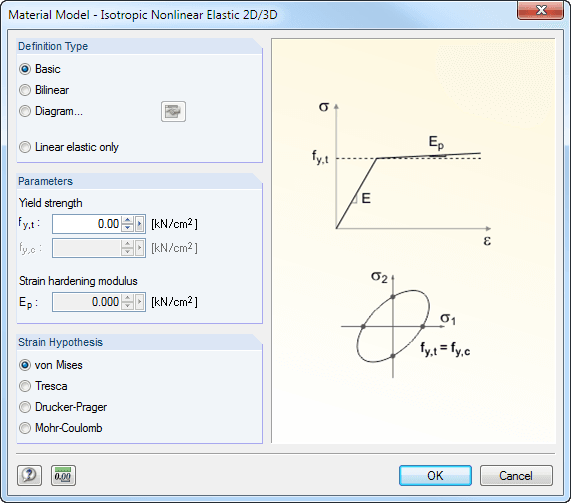
The following material models are available in RF − MAT NL:
Isotropic Plastic 1D/2D/3D and Isotropic Nonlinear Elastic 1D/2D/3D
You can select three different definition types here:
- Basic (definition of the equivalent stress under which the material plastifies)
- Bilinear (definition of the equivalent stress and strain hardening modulus)
- Diagram:
- Definition of polygonal stress-strain diagram
- Option to save / import the diagram
- Interface with MS Excel
Orthotropic Plastic 2D/3D (Tsai-Wu 2D/3D)
This material model allows the definition of material properties (modulus of elasticity, shear modulus, Poisson's ratio) and ultimate strengths (tension, compression, shear) in two or three axes.
Isotropic Masonry 2D
It is possible to specify the limit tension stresses σx,limit and σy,limit as well as the hardening factor CH.
Orthotropic Masonry 2D
The material model Orthotropic Masonry 2D is an elastoplastic model that additionally allows softening of the material, which can be different in the local x- and y-directions of a surface. The material model is suitable for (unreinforced) masonry walls with in-plane loads.
Isotropic Damage 2D/3D
Here, you can define antimetric stress-strain diagrams. The modulus of elasticity is calculated in each step of the stress-strain diagram using Ei = (σi -σi-1 )/(εi -εi-1 ).
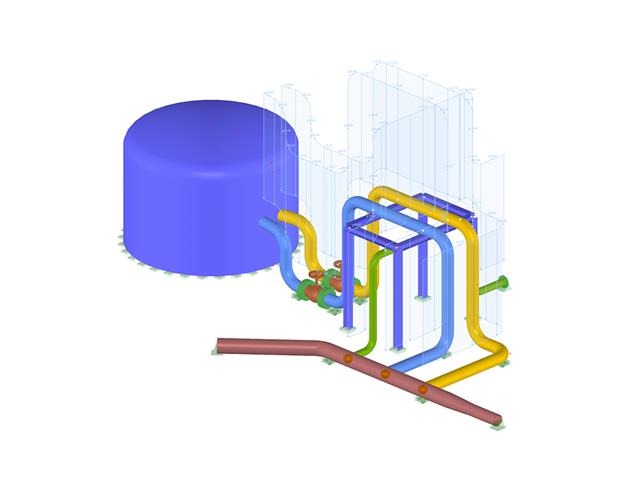
- Graphical input of piping systems and piping components
- Illustrative visualization of piping systems and piping components in RFEM graphic window
- Comprehensive libraries for piping cross‑sections and materials
- Comprehensive libraries for flanges, reducers, tees, and expansion joints
- Consideration of piping structure (insulation, lining, tin‑plate)
- Automatic calculation of stress intensification factors and flexibility factors
- Specific piping action categories for load cases
- Optional automatic combinatorics of load cases
- Consideration of material properties (modulus of elasticity, coefficient of thermal expansion) either during operating temperature (default setting) or during reference (assembly) temperature of material
- Consideration of strain and uplift due to pressure (Bourdon effect)
- Interaction between the supporting structure and the piping system
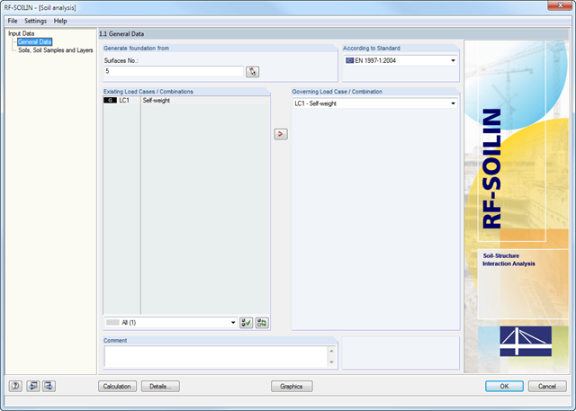
The definition of soil layers is performed in a clearly arranged input window. An extensible library facilitates the selection of soil properties.
The elasticity can be defined either by the stiffness modulus or the modulus of elasticity and the Poisson's ratio. It is possible to define any number of soil layers. You can assign the layers to the building graphically or by entering the relevant coordinates.